
Me ha gustado mucho la facilidad de uso (y sobre todo el precio) de este dispositivo. El ESP8266 puede dotar a nuestros proyectos de la conectividad que necesitaban y así adentrarnos en el Internet de las cosas o IoT.
Lo primero es sentirnos cómodos con el entorno. Así que voy a proponer dos opciones. La primera, multiplataforma será utilizando el mismo entorno Arduino. En este caso, al final del proceso cuando estemos compilando o subiendo el código a nuestro chip seleccionaremos la placa ESP8266 y compilaremos para ella. Podremos conectar el ESP8266 con un adaptador USB-UART o incluso desde el propio Arduino. Para ver cómo debemos conectarlo, visita el post sobre programación del ESP8266.
Tabla de contenidos
- 1 Instalación en el entorno Arduino
- 2 Instalación independiente
- 3 Compilando ejemplos
- 4 Problemas y soluciones
- 5 También podría interesarte....
Instalación en el entorno Arduino
Como dije antes es la opción más cómoda y nos va a funcionar sea cual sea nuestro sistema operativo. De manera muy parecida a como hice en este post sobre la programación de ATtinys, podemos añadir esta URL para gestionar tarjetas en Archivo / Preferencias:
http://arduino.esp8266.com/stable/package_esp8266com_index.json
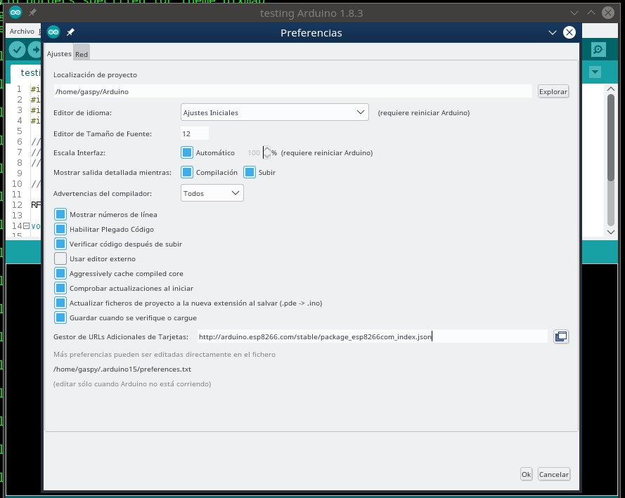
Tras esto, vamos a Herramientas / Placa / Gestor de tarjetas y buscamos ESP8266. Con lo que debería salirnos algo así:
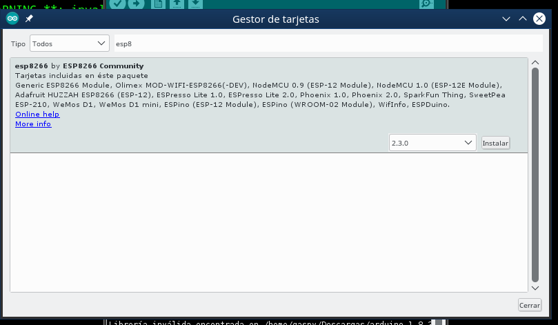
Seguidamente seleccionamos el módulo y lo instalamos. El software ocupa cerca de 150Mb, entre bibliotecas, programas para compilar y programar, cabeceras y demás, así que tenemos que tener en cuenta el espacio que necesitaremos. Y tardará un rato entre la descarga de los módulos y la configuración.
Con Arduino no es muy duro, ¿eh? En este punto ya podemos crear cualquier programa para nuestro chip y subirlo sin complicación desde el entorno del que estamos acostumbrados. Además, desde el entorno Arduino podemos aprovecharnos de muchas facilidades que nos brinda el lenguaje, por ejemplo el Serial lo podemos programar de forma más parecida a como lo hacemos en un Atmega con las abstracciones que nos proporciona Arduino. El programa ocupará un poco más, ya que tenemos las abstracciones propias de Arduino y algunas bibliotecas y atajos de enlazado muy interesantes. Aunque los compiladores son muy listos a estas alturas y todo lo que subamos estará optimizado en tamaño.
Instalación independiente
Pero claro, no todo es Arduino y su ecosistema. Si de verdad queremos tener algo más de control sobre las biliotecas, la compilación, la programación y demás, nos vendrá realmente bien la instalación manual del software.
He utilizado Linux Mint 18.2 para realizar esta instalación, aunque debería ser muy parecido en Ubuntu, Debian y otras. Los nombres de los paquetes también suelen ser parecidos entre distribuciones (no los mismos, pero al menos se pueden encontrar más o menos fácil).
Instalar dependencias
Antes de nada vamos a ver qué necesitamos para instalar nuestro entorno. Lo primero, unos 4Gb de disco libres, porque vamos a copiar mucho código fuente y documentación.
Tras ello, instalaremos el software necesario que puede venir con nuestra distribución GNU/Linux:
Instalar software
Aunque podemos realizar el proceso de forma manual, vamos a utilizar esp-open-sdk. Aquí voy a poner algunas instrucciones sencillas para instalarlo. Pero podremos personalizar la instalación y hacer algunas cosas más. Leed el manual, que hay cosas muy interesantes, pero si queréis algo rápido:
Tardará un rato porque tendremos que descargar muchas cosas (a mí me tardó unos 10 minutos más o menos).
Luego, es buena idea incluir en nuestro archivo /home/USUARIO/.profile lo siguiente:
PATH=»$HOME/local/opt/stand/esp-open-sdk/xtensa-lx106-elf/bin:$PATH»
En mi caso, yo instalé todos los programas en $HOME/local/opt/stand/esp-open-sdk/ deberás cambiar este directorio por tu directorio de instalación. Esta línea en .profile sirve para que podamos ejecutar las utilidades instaladas en las próximas sesiones estemos donde estemos sin necesidad de hacer export PATH=…
Compilando ejemplos
Ya que tenemos el entorno preparado, vamos a proceder a compilar algunos de los ejemplos que vienen (y algunos otros que me he inventado) para hacer pruebas. Primero, vamos a compilar un programa de led intermitente, un blink para ver que todo funciona bien. Al menos, si vemos el led haciendo intermitencia, es que todo funciona perfectamente. De todas formas, al final del post veremos algunos problemas con los que me he encontrado.
Blinky a mano
Una vez instalamos esp-open-sdk dentro del directorio examples encontramos blinky. El famoso ejemplo de un led intermitente, algo así como un hola mundo, en el que podemos ver si nuestros programas compilan bien y si se suben bien, además, veremos el chip funcionando.
Puede que en futuras versiones no encontremos este ejemplo, o incluso aparezca modificado, aśi que pondré aquí el contenido de blinky.c:
1 2 3 4 5 6 7 8 9 10 11 12 13 14 15 16 17 18 19 20 21 22 23 24 25 26 27 28 29 30 31 32 33 34 35 36 | #include "ets_sys.h" #include "osapi.h" #include "gpio.h" #include "os_type.h" static const int pin = 1; static volatile os_timer_t some_timer; void some_timerfunc(void *arg) { //Do blinky stuff if (GPIO_REG_READ(GPIO_OUT_ADDRESS) & (1 << pin)) { // set gpio low gpio_output_set(0, (1 << pin), 0, 0); } else { // set gpio high gpio_output_set((1 << pin), 0, 0, 0); } } void ICACHE_FLASH_ATTR user_init() { // init gpio subsytem gpio_init(); // configure UART TXD to be GPIO1, set as output PIN_FUNC_SELECT(PERIPHS_IO_MUX_U0TXD_U, FUNC_GPIO1); gpio_output_set(0, 0, (1 << pin), 0); // setup timer (500ms, repeating) os_timer_setfn(&some_timer, (os_timer_func_t *)some_timerfunc, NULL); os_timer_arm(&some_timer, 500, 1); } |
Está pensado para cargarlo en un ESP8266-01 por lo que el led está en el GPIO01, que es el led azul que indica transmisión de datos. Al mismo tiempo ese puerto coincide con la transmisión de datos del puerto serie. Así que, cuando lo ejecutemos, al mismo tiempo que veremos el led parpadeando (si todo funciona bien), si abrimos una ventana serie mientras tenemos el chip enchufado en el ordenador veremos cómo recibimos datos en la consola.
Aunque el ejemplo trae un fichero Makefile, con el que simplemente haciendo make debe funcionar, quiero repasar todo lo necesario para compilar, generar un fichero binario y subir el fichero a nuestro dispositivo:
¿Por qué tanta complicación? Casi todo son bibliotecas, aunque veamos:
- xtensa-lx106-elf-gcc : Es el compilador, la versión que hemos instalado de gcc.
- -mlongcalls : A veces, cuando se traduce el código C a ensamblador, hay llamadas a funciones o a direcciones de memoria que no se pueden hacer directamente, porque están en posiciones de memoria lejanas.
- -o blinky : El fichero binario de destino se llamará sólo blinky.
- blinky.c : Es nuestro fichero fuente. Esta vez sólo tenemos uno. Aunque cuando tengamos más archivos utilizaremos siempre un Makefle en lugar de pelearnos con todos aquí, aunque podríamos incluir una sere de archivos .c desde aquí.
- -Teagle.app.v6.ld : Para realizar el linkado vamos a utilizar un script del SDK del ESP8266 llamado eagle.app.v6.ld. Esto podrá variar en el futuro.
- -nostdlib : No incluiremos la biblioteca estándar de C, ya que el SDK tiene su propia implementación.
- -Wl,–start-group …. -Wl,–end-group : Lo que empieza por -Wl,… serán argumentos que le pasaremos al linker, es decir, el que asocia las llamadas que hacemos a funciones de biblioteca con las bibliotecas en cuestión. El hecho de utilizar grupos en el linker de GCC evita que tengamos que repetir el linkado de bibliotecas si, por ejemplo hay referencias cruzadas entre las propias bibliotecas. Es decir, que las bibliotecas hagan llamadas a funciones que están en otras bibliotecas por lo que tendríamos que linkarlas de nuevo. Se pueden añadir de nuevo en la línea de GCC, pero queda feo hacerlo.
- -lmail , -lnet80211 , -lwpa … : Todas estas serán bibliotecas que encontramos dentro del SDK. Dentro de sdk/lib están todas. Y seguramente para nuestros proyectos futuros utilizaremos alguna de ellas.
Esto generará la imagen que tenemos que grabar en la memoria flash de nuestro chip. Seguidamente, conectaremos nuestro ESP8266 tal y como lo hicimos en este post para flashear el firmware:

Y ejecutamos:
Tras ello, desconectamos los pins GPIO0 y GPIO2 (que estaban en modo programación). Desconectamos la corriente y la volvemos a conectar. Debemos ver el dispositivo con el led intermitente.
Utilizando C99, C11 y C++
Podemos utilizar también revisiones nuevas del lenguaje de programación C. Sin problema. El caso es que, como todavía quedan resquicios privativos en las bibliotecas del chip y, parece ser, que no se han publicado aún muchas cosas, hay funciones cuya cabecera no está disponible. Así que varias comunidades dedicadas al ESP8266 (y ESP32, que es la siguiente versión), han decidido crear un archivo llamado espmissingincludes.h; se puede buscar por Internet, aunque una de las versiones que más me convence es esta:
1 2 3 4 5 6 7 8 9 10 11 12 13 14 15 16 17 18 19 20 21 22 23 24 25 26 27 28 29 30 31 32 33 34 35 36 37 38 39 40 41 42 43 44 45 46 47 48 49 50 51 52 53 54 55 56 57 58 59 60 61 62 63 64 65 66 67 68 69 70 71 72 73 74 75 76 77 78 79 80 81 82 83 84 85 86 87 88 89 90 91 92 93 94 95 96 97 98 | #ifndef ESPMISSINGINCLUDES_H #define ESPMISSINGINCLUDES_H #include <user_interface.h> #include <eagle_soc.h> #include <stdint.h> #include <c_types.h> #include <ets_sys.h> #include <stdarg.h> #ifdef __cplusplus extern "C" { #endif //Missing function prototypes in include folders. Gcc will warn on these if we don't define 'em anywhere. //MOST OF THESE ARE GUESSED! but they seem to work and shut up the compiler. typedef struct espconn espconn; /*bool wifi_station_set_hostname(char *); char *wifi_station_get_hostname(void); */ int atoi(const char *nptr); //void ets_install_putc1(void *routine); // necessary for #define os_xxx -> ets_xxx //void ets_isr_attach(int intr, void *handler, void *arg); void ets_isr_mask(unsigned intr); void ets_isr_unmask(unsigned intr); int ets_memcmp(const void *s1, const void *s2, size_t n); void *ets_memcpy(void *dest, const void *src, size_t n); void *ets_memmove(void *dest, const void *src, size_t n); void *ets_memset(void *s, int c, size_t n); int ets_sprintf(char *str, const char *format, ...) __attribute__ ((format (printf, 2, 3))); int ets_str2macaddr(void *, void *); int ets_strcmp(const char *s1, const char *s2); char *ets_strcpy(char *dest, const char *src); //size_t ets_strlen(const char *s); //int ets_strncmp(const char *s1, const char *s2, int len); char *ets_strncpy(char *dest, const char *src, size_t n); char *ets_strstr(const char *haystack, const char *needle); void ets_timer_arm_new(volatile ETSTimer *a, int b, int c, int isMstimer); void ets_timer_disarm(volatile ETSTimer *a); void ets_timer_setfn(volatile ETSTimer *t, ETSTimerFunc *fn, void *parg); void ets_update_cpu_frequency(int freqmhz); #ifdef SDK_DBG #define DEBUG_SDK true #else #define DEBUG_SDK false #endif int ets_vsprintf(char *str, const char *format, va_list argptr); int ets_vsnprintf(char *buffer, size_t sizeOfBuffer, const char *format, va_list argptr); int os_snprintf(char *str, size_t size, const char *format, ...) __attribute__((format(printf, 3, 4))); int os_printf_plus(const char *format, ...) __attribute__((format(printf, 1, 2))); // memory allocation functions are "different" due to memory debugging functionality // added in SDK 1.4.0 //void vPortFree(void *ptr, const char * file, int line); //void *pvPortMalloc(size_t xWantedSize, const char * file, int line); //void *pvPortZalloc(size_t, const char * file, int line); void *vPortMalloc(size_t xWantedSize); void pvPortFree(void *ptr); //void uart_div_modify(int no, unsigned int freq); //uint32 system_get_time(); int rand(void); void ets_bzero(void *s, size_t n); void ets_delay_us(int ms); // disappeared in SDK 1.1.0: #define os_timer_done ets_timer_done #define os_timer_handler_isr ets_timer_handler_isr #define os_timer_init ets_timer_init // This is not missing in SDK 1.1.0 but causes a parens error #undef PIN_FUNC_SELECT #define PIN_FUNC_SELECT(PIN_NAME, FUNC) do { \ WRITE_PERI_REG(PIN_NAME, \ (READ_PERI_REG(PIN_NAME) & ~(PERIPHS_IO_MUX_FUNC<<PERIPHS_IO_MUX_FUNC_S)) \ |( (((FUNC&BIT2)<<2)|(FUNC&0x3))<<PERIPHS_IO_MUX_FUNC_S) ); \ } while (0) // Shortcuts for memory functions //#define os_malloc pvPortMalloc // defined in SDK 1.4.0 onwards //#define os_free vPortFree // defined in SDK 1.4.0 onwards //#define os_zalloc pvPortZalloc // defined in SDK 1.4.0 onwards //uint8 wifi_get_opmode(void); // defined in SDK 1.0.0 onwards //int os_random(); // defined in SDK 1.1.0 onwards #ifdef __cplusplus } #endif #endif |
Este archivo debemos incluirlo en nuestro archivo .c del programa. Y ahora sí que nos dejará compilar con algo así:
Con lo que podremos utilizar características del lenguaje C mucho más modernas.
¿Qué hay de C++?
Bueno, el SDK del ESP8266 está hecho en C y las funciones que se llamen desde la biblioteca (como por ejemplo user_init(), deben estar enlazadas en C. Por eso, vamos a utilizar:
1 2 3 4 5 6 7 8 9 10 11 | extern "C" { // Aquí van los includes de la biblioteca } // Aquí va el código C++ que vayamos a utilizar. extern "C" { // Aquí van las funciones que se llamen desde la biblioteca. } |
Así, nuestro blinky.cpp quedaría así:
1 2 3 4 5 6 7 8 9 10 11 12 13 14 15 16 17 18 19 20 21 22 23 24 25 26 27 28 29 30 31 32 33 34 35 36 37 38 39 40 41 42 43 44 45 46 47 48 49 50 51 | extern "C" { #include "ets_sys.h" #include "osapi.h" #include "gpio.h" #include "os_type.h" #include "espmissingincludes.h" } // ESP-12 modules have LED on GPIO2. Change to another GPIO // for other boards. static const int pin = 1; static volatile os_timer_t some_timer; void some_timerfunc(void *arg) { //Do blinky stuff if (GPIO_REG_READ(GPIO_OUT_ADDRESS) & (1 << pin)) { // set gpio low gpio_output_set(0, (1 << pin), 0, 0); } else { // set gpio high gpio_output_set((1 << pin), 0, 0, 0); } } LOCAL void ICACHE_FLASH_ATTR set_blink_timer() { // Start a timer for the flashing of the LED on GPIO 4, running continuously. os_timer_setfn(&some_timer, (os_timer_func_t *)some_timerfunc, NULL); os_timer_arm(&some_timer, 500, 1); } extern "C" { void ICACHE_FLASH_ATTR user_init() { // init gpio subsytem gpio_init(); // configure UART TXD to be GPIO1, set as output PIN_FUNC_SELECT(PERIPHS_IO_MUX_U0TXD_U, FUNC_GPIO1); gpio_output_set(0, 0, (1 << pin), 0); // setup timer (500ms, repeating) set_blink_timer(); } } |
Y… ¡ya podemos utilizar clases! Bueno, y algunas características de C++, incluso de C++11. la pega es que no podemos utilizar la biblioteca std, ni string, ni map, ni vector… una pena. De todas formas, no es imposible. Es un problema al enlazar la biblioteca estándar de C++, porque necesita funciones de C. Podríamos crear dichas funciones con las herramientas que tenemos o buscar versiones reducidas de las clases que necesitamos (que seguramente ocupen menos en memoria), o utilizar la construcción desde Arduino (aunque he de escudriñar un poco más el proceso que sigue Arduino para incluir la biblioteca de C++)
Un Makefile y estructura genericos para nuestros programas
Después de investigar un tiempo con el dispositivo en mis manos y probar algunas formas de construir fácilmente nuestros programas. Además, hacerlos de una forma independiente del editor o IDE que estemos utilizando. Lo primero será crear una estructura de directorios y archivos lógica y manejable para poder utilizar sin problemas. Muchas de las estructuras y ejemplos las estoy publicando en GitHub por lo que, si no hay ningún post nuevo sobre el tema, aquí encontraréis la última versión.
La estructura básica de un proyecto, es decir, dentro del directorio del proyecto encontraremos:
|
|- user/ (directorio con los ficheros de nuestro programa)
| |- user_main.c (fichero principal del programa)
| |- user_config.h (fichero de configuración (claves, ssid, contraseñas, o todas esas cosas relativas a configuración. Este archivo podrá estar vacío.)
| |_ (resto de ficheros del programa, .c y .h)
|- include/ (ficheros .h interesantes)
| |- espmissingincludes.h (el fichero que vimos antes con los símbolos que no tenía el SDK)
| |- driver/ (includes de drivers)
| |_ (resto de includes, ficheros de definiciones de bibliotecas, etc)
|- driver/ (drivers de dispositivos, tanto software como hardware que usemos en nuestro proyecto)
|- build/ (ficheros compilados, será un directorio interno donde se almacene todo lo que vayamos compilando)
|- firmware/ (ficheros de firmware, listos para ser copiados al chip)
|- Makefile (fichero con las instrucciones para construir el programa)
|- README (fichero de texto con instrucciones, explicaciones y demás)
|- …
Podremos incluir ficheros como LICENSE (con la licencia), CHANGELOG (con el registro de cambios) o algún otro script más que nos ayude a construir. Así como un directorio lib/ donde podamos copiar todas esas bibliotecas extra que vayamos a utilizar en el proyecto. Pero creo que ésta es una buena estructura básica para empezar.
Con drivers me refiero a todo lo referente al UART, SPI, temporizador, o incluso herramientas de control o incluso programas que obtengan resultados de sensores, hablen con displays, etc.
Ahora os pongo un ejemplo de Makefile:
1 2 3 4 5 6 7 8 9 10 11 12 13 14 15 16 17 18 19 20 21 22 23 24 25 26 27 28 29 30 31 32 33 34 35 36 37 38 39 40 41 42 43 44 45 46 47 48 49 50 51 52 53 54 55 56 57 58 59 60 61 62 63 64 65 66 67 68 69 70 71 72 73 74 75 76 77 78 79 80 81 82 83 84 85 86 87 88 89 90 91 92 93 94 95 96 97 98 99 100 101 102 103 104 105 106 107 108 109 110 111 112 113 114 115 116 117 118 119 120 121 122 123 124 125 126 127 128 129 130 131 132 133 134 135 136 137 | # Makefile for ESP8266 projects # # Thanks to: # - zarya # - Jeroen Domburg (Sprite_tm) # - Christian Klippel (mamalala) # - Tommie Gannert (tommie) # # Changelog: # - 2014-10-06: Changed the variables to include the header file directory # - 2014-10-06: Added global var for the Xtensa tool root # - 2014-11-23: Updated for SDK 0.9.3 # - 2014-12-25: Replaced esptool by esptool.py # Output directors to store intermediate compiled files # relative to the project directory BUILD_BASE = build FW_BASE = firmware # base directory for the compiler XTENSA_TOOLS_ROOT ?= ~/local/opt/stand/esp-open-sdk/xtensa-lx106-elf/bin # base directory of the ESP8266 SDK package, absolute SDK_BASE ?= ~/local/opt/stand/esp-open-sdk/sdk # esptool.py path and port ESPTOOL ?= esptool.py ESPPORT ?= /dev/ttyACM0 # name for the target project TARGET = app # which modules (subdirectories) of the project to include in compiling MODULES = driver user EXTRA_INCDIR = driver include # libraries used in this project, mainly provided by the SDK LIBS = c gcc hal pp phy net80211 lwip wpa main # compiler flags using during compilation of source files CFLAGS = -Os -O2 -Wpointer-arith -Wundef -Werror -Wl,-EL -fno-inline-functions -nostdlib -mlongcalls -mtext-section-literals -D__ets__ -DICACHE_FLASH # linker flags used to generate the main object file LDFLAGS = -nostdlib -Wl,--no-check-sections -u call_user_start -Wl,-static # linker script used for the above linkier step LD_SCRIPT = eagle.app.v6.ld # various paths from the SDK used in this project SDK_LIBDIR = lib SDK_LDDIR = ld SDK_INCDIR = include include/json # we create two different files for uploading into the flash # these are the names and options to generate them FW_FILE_1_ADDR = 0x00000 FW_FILE_2_ADDR = 0x10000 # select which tools to use as compiler, librarian and linker CC := $(XTENSA_TOOLS_ROOT)/xtensa-lx106-elf-gcc AR := $(XTENSA_TOOLS_ROOT)/xtensa-lx106-elf-ar LD := $(XTENSA_TOOLS_ROOT)/xtensa-lx106-elf-gcc #### #### no user configurable options below here #### SRC_DIR := $(MODULES) BUILD_DIR := $(addprefix $(BUILD_BASE)/,$(MODULES)) SDK_LIBDIR := $(addprefix $(SDK_BASE)/,$(SDK_LIBDIR)) SDK_INCDIR := $(addprefix -I$(SDK_BASE)/,$(SDK_INCDIR)) SRC := $(foreach sdir,$(SRC_DIR),$(wildcard $(sdir)/*.c)) OBJ := $(patsubst %.c,$(BUILD_BASE)/%.o,$(SRC)) LIBS := $(addprefix -l,$(LIBS)) APP_AR := $(addprefix $(BUILD_BASE)/,$(TARGET)_app.a) TARGET_OUT := $(addprefix $(BUILD_BASE)/,$(TARGET).out) LD_SCRIPT := $(addprefix -T$(SDK_BASE)/$(SDK_LDDIR)/,$(LD_SCRIPT)) INCDIR := $(addprefix -I,$(SRC_DIR)) EXTRA_INCDIR := $(addprefix -I,$(EXTRA_INCDIR)) MODULE_INCDIR := $(addsuffix /include,$(INCDIR)) FW_FILE_1 := $(addprefix $(FW_BASE)/,$(FW_FILE_1_ADDR).bin) FW_FILE_2 := $(addprefix $(FW_BASE)/,$(FW_FILE_2_ADDR).bin) V ?= $(VERBOSE) ifeq ("$(V)","1") Q := vecho := @true else Q := @ vecho := @echo endif vpath %.c $(SRC_DIR) define compile-objects $1/%.o: %.c $(vecho) "CC $$<" $(Q) $(CC) $(INCDIR) $(MODULE_INCDIR) $(EXTRA_INCDIR) $(SDK_INCDIR) $(CFLAGS) -c $$< -o $$@ endef .PHONY: all checkdirs flash clean all: checkdirs $(TARGET_OUT) $(FW_FILE_1) $(FW_FILE_2) $(FW_BASE)/%.bin: $(TARGET_OUT) | $(FW_BASE) $(vecho) "FW $(FW_BASE)/" $(Q) $(ESPTOOL) elf2image -o $(FW_BASE)/ $(TARGET_OUT) $(TARGET_OUT): $(APP_AR) $(vecho) "LD $@" $(Q) $(LD) -L$(SDK_LIBDIR) $(LD_SCRIPT) $(LDFLAGS) -Wl,--start-group $(LIBS) $(APP_AR) -Wl,--end-group -o $@ $(APP_AR): $(OBJ) $(vecho) "AR $@" $(Q) $(AR) cru $@ $^ checkdirs: $(BUILD_DIR) $(FW_BASE) $(BUILD_DIR): $(Q) mkdir -p $@ $(FW_BASE): $(Q) mkdir -p $@ flash: $(FW_FILE_1) $(FW_FILE_2) $(ESPTOOL) --port $(ESPPORT) write_flash $(FW_FILE_1_ADDR) $(FW_FILE_1) $(FW_FILE_2_ADDR) $(FW_FILE_2) clean: $(Q) rm -rf $(FW_BASE) $(BUILD_BASE) $(foreach bdir,$(BUILD_DIR),$(eval $(call compile-objects,$(bdir)))) |
Para este archivo, en cada proyecto tendremos que cambiar XTENSA_TOOLS_ROOT y SDK_BASE para que apunten a las rutas correctas dentro de nuestro ordenador.
Con este Makefile haremos que con sencillos comandos podamos realizar diferentes tareas:
- make : Construye el programa (compila, linka y crea los binarios que vamos a flashear).
- make clean : Limpia los ficheros objeto creados, para volver a construir desde cero.
- make flash : Sube los binarios al chip.
- make flash ESPPORT=/dev/ttyUSB0 : Cambia el puerto serie para flashear.
Ejemplo de uso del UART (el serial USB)
Encontramos el ejemplo aquí. Para hacer la comunicación por los puertos RX y TX del UART0 he copiado el driver UART que encontramos en el SDK:
- sdk/driver_lib/include/driver/uart.h a include/driver/
- sdk/driver_lib/include/driver/uart_register.h a include/driver/
- sdk/driver_lib/driver/uart.c a driver/
De esta forma tendremos acceso al UART. Podríamos programarlo nosotros, pero el SDK ya trae una buena forma de hacerlo, y una serie de constantes predefinidas que serán de mucha ayuda. Eso sí, ahora tendremos que hacer algunos cambios en el driver uart.c:
Establecer prioridad de la tarea
Debemos ajustar la prioridad de acuerdo a nuestro programa, encontraremos al principio del archivo algo así:
1 2 | /*it might conflict with your task, if so,please arrange the priority of different task, or combine it to a different event in the same task. */ #define uart_recvTaskPrio 1 |
La directiva uart_recvTaskPrio deberá valer 0, 1, 2 o 3. Intenta que no haya conflictos con las tareas que ya tenga tu programa.
Declaración de la tarea externa
Lo siguiente será crear una declaración de la tarea de recepción. Aunque el driver ya trae una tarea que se lanza cuando se reciben mensajes desde el UART, queremos tener una tarea propia para procesarlos a nuestro gusto. Y esa tarea la definiremos en el código fuente de nuestro programa más adelante. La tarea actual se llama uart_recvTask, así que podemos borrarlo si queremos.
1 2 | // uart_rx_task is defined in the main code. void uart_rx_task(os_event_t *); |
Inicialización de la tarea
En uart_init() debemos llamar a la tarea correcta:
1 | system_os_task(uart_rx_task, uart_recvTaskPrio, uart_recvTaskQueue, uart_recvTaskQueueLen); //demo with a task to process the uart data |
Código del programa
Dejo aquí el código fuente de user_main.c:
1 2 3 4 5 6 7 8 9 10 11 12 13 14 15 16 17 18 19 20 21 22 23 24 25 26 27 28 29 30 31 32 33 34 35 36 37 38 39 40 41 42 43 44 45 46 47 48 49 50 51 52 53 54 55 56 57 58 59 60 61 62 63 64 65 66 67 68 69 70 71 72 73 74 75 76 77 78 79 80 81 82 83 84 85 86 87 88 89 90 91 92 93 94 95 96 97 98 99 100 101 | /* Picked up a blinky.c and converted it in an ECHO por ESP8266 UART. */ #include "ets_sys.h" #include "osapi.h" #include "gpio.h" #include "os_type.h" #include "user_config.h" #include "driver/uart.h" #include "user_interface.h" #define BLINK_BIT BIT2 #define MAX_RX_DATA_SIZE 32 #define user_procTaskPrio 2 #define user_procTaskQueueLen 1 os_event_t user_procTaskQueue[user_procTaskQueueLen]; static void user_procTask(os_event_t *events); static volatile os_timer_t some_timer; void some_timerfunc(void *arg) { //Do blinky stuff if (GPIO_REG_READ(GPIO_OUT_ADDRESS) & BLINK_BIT) { //Set GPIO2 to LOW gpio_output_set(0, BLINK_BIT, BLINK_BIT, 0); } else { //Set GPIO2 to HIGH gpio_output_set(BLINK_BIT, 0, BLINK_BIT, 0); } } void post_rx_action(char* data) { ets_printf ("Received: %s\n", data); } void ICACHE_FLASH_ATTR uart_rx_task(os_event_t *events) { if (events->sig == 0) { // Sig 0 is a normal receive. Get how many bytes have been received. uint8_t rx_len = (READ_PERI_REG(UART_STATUS(UART0)) >> UART_RXFIFO_CNT_S) & UART_RXFIFO_CNT; // Parse the characters, taking any digits as the new timer interval. char rx_data[MAX_RX_DATA_SIZE]; uint8_t i; for (i=0; i < MAX_RX_DATA_SIZE-1; i++) { rx_data[i] = READ_PERI_REG(UART_FIFO(UART0)) & 0xFF; } rx_data[(rx_len>MAX_RX_DATA_SIZE-1)?MAX_RX_DATA_SIZE-1:rx_len]='\0'; post_rx_action(rx_data); // Clear the interrupt condition flags and re-enable the receive interrupt. WRITE_PERI_REG(UART_INT_CLR(UART0), UART_RXFIFO_FULL_INT_CLR | UART_RXFIFO_TOUT_INT_CLR); uart_rx_intr_enable(UART0); } } //Do nothing function static void ICACHE_FLASH_ATTR user_procTask(os_event_t *events) { os_delay_us(10); } //Init function void ICACHE_FLASH_ATTR user_init() { // Disable debug system_set_os_print(0); // Initialize the GPIO subsystem. gpio_init(); uart_init(BIT_RATE_115200, BIT_RATE_115200); // Disable WiFi wifi_station_disconnect(); wifi_set_opmode(NULL_MODE); wifi_set_sleep_type(MODEM_SLEEP_T); //Set GPIO2 to output mode (BLINK_BIT) PIN_FUNC_SELECT(PERIPHS_IO_MUX_GPIO2_U, FUNC_GPIO2); //Set GPIO2 low gpio_output_set(0, BLINK_BIT, BLINK_BIT, 0); //Disarm timer os_timer_disarm(&some_timer); //Setup timer os_timer_setfn(&some_timer, (os_timer_func_t *)some_timerfunc, NULL); //Arm the timer os_timer_arm(&some_timer, 1000, 1); //Start os task /* system_os_task(user_procTask, user_procTaskPrio,user_procTaskQueue, user_procTaskQueueLen); */ } |
Vemos que en este ejemplo desactivo por completo la red inalámbrica (como no la queremos, ahorra energía. También desactivo la depuración por lo que os_printf() no tendría efecto, además, nos quitamos muchos mensajes que envía el dispositivo con el fin de saber lo que está haciendo el chip o por qué ha fallado… no está bien para hacer pruebas, pero sí para producción y, por ejemplo si nos vamos a comunicar mediante este puerto serie con otro chip (al otro chip tal vez no le guste demasiado tener información que no sabe interpretar).
Intérprete de comandos
Vamos a implementar un pequeño intérprete de comandos en el que podamos enviar y recibir texto por el UART y obtengamos un resultado. Como puede ser una respuesta en función de lo pedido. Este ejemplo puede generar varios comandos, cada uno asociado a un callback:
- HELLO: Responderá «Hello Dude!»
- REPEAT [loquesea]: Responderá «Repeating: loquesea
- INFO: Responderá con información sobre algunas variables del sistema como tiempo online, memoria libre, versión del SDK, etc.
Los comandos son ampliables fácilmente, sólo hay que añadir un callback y llamar a add_command(). De todas formas es algo muy sencillo y no creo que sea apto para estar en producción. He creado varios archivos.
utils.h:
1 2 3 4 5 6 7 8 9 10 | #ifndef UTILS_H #define UTILS_H #include <c_types.h> char * dtostrf(double number, signed char width, unsigned char prec, char *s); int os_snprintf(char* buffer, size_t size, const char* format, ...); char* timeInterval(char* buffer, size_t bufferSize, unsigned long seconds); #endif |
utils.c:
1 2 3 4 5 6 7 8 9 10 11 12 13 14 15 16 17 18 19 20 21 22 23 24 25 26 27 28 29 30 31 32 33 34 35 36 37 38 39 40 41 42 43 44 45 46 47 48 49 50 51 52 53 54 55 56 57 58 59 60 61 62 63 64 65 66 67 68 69 70 71 72 73 74 75 76 77 78 79 80 81 82 83 84 85 86 87 88 89 90 91 92 93 94 95 96 97 | #include "espmissingincludes.h" #include "math.h" #include "ets_sys.h" #include "osapi.h" #include <stdarg.h> char * dtostrf(double number, signed char width, unsigned char prec, char *s) { bool negative = false; if (isnan(number)) { strcpy(s, "nan"); return s; } if (isinf(number)) { strcpy(s, "inf"); return s; } char* out = s; int fillme = width; // how many cells to fill for the integer part if (prec > 0) { fillme -= (prec+1); } // Handle negative numbers if (number < 0.0) { negative = true; fillme--; number = -number; } // Round correctly so that print(1.999, 2) prints as "2.00" // I optimized out most of the divisions double rounding = 2.0; for (uint8_t i = 0; i < prec; ++i) rounding *= 10.0; rounding = 1.0 / rounding; number += rounding; // Figure out how big our number really is double tenpow = 1.0; int digitcount = 1; while (number >= 10.0 * tenpow) { tenpow *= 10.0; digitcount++; } number /= tenpow; fillme -= digitcount; // Pad unused cells with spaces while (fillme-- > 0) { *out++ = ' '; } // Handle negative sign if (negative) *out++ = '-'; // Print the digits, and if necessary, the decimal point digitcount += prec; int8_t digit = 0; while (digitcount-- > 0) { digit = (int8_t)number; if (digit > 9) digit = 9; // insurance *out++ = (char)('0' | digit); if ((digitcount == prec) && (prec > 0)) { *out++ = '.'; } number -= digit; number *= 10.0; } // make sure the string is terminated *out = 0; return s; } int os_snprintf(char* buffer, size_t size, const char* format, ...) { int ret; va_list arglist; va_start(arglist, format); ret = ets_vsnprintf(buffer, size, format, arglist); va_end(arglist); return ret; } char* timeInterval(char* buffer, size_t bufferSize, unsigned long seconds) { uint16_t hours = seconds / 3600, rem = seconds % 3600, minutes = rem / 60, secs = rem % 60; os_snprintf (buffer, bufferSize, "%d:%d:%d", hours, minutes, secs); return buffer; } |
La función dtostrf() la he cogido de las bibliotecas de Arduino.
user_main.c:
1 2 3 4 5 6 7 8 9 10 11 12 13 14 15 16 17 18 19 20 21 22 23 24 25 26 27 28 29 30 31 32 33 34 35 36 37 38 39 40 41 42 43 44 45 46 47 48 49 50 51 52 53 54 55 56 57 58 59 60 61 62 63 64 65 66 67 68 69 70 71 72 73 74 75 76 77 78 79 80 81 82 83 84 85 86 87 88 89 90 91 92 93 94 95 96 97 98 99 100 101 102 103 104 105 106 107 108 109 110 111 112 113 114 115 116 117 118 119 120 121 122 123 124 125 126 127 128 129 130 131 132 133 134 135 136 137 138 139 140 141 142 143 144 145 146 147 148 149 150 151 152 153 154 155 156 157 158 159 160 161 162 163 164 165 166 167 168 169 170 171 172 173 174 175 176 177 178 179 180 181 182 183 184 185 186 187 188 189 190 191 192 193 194 195 196 197 198 199 200 201 202 203 204 205 206 207 208 209 210 211 212 213 214 215 216 217 218 219 220 | /* Picked up a blinky.c and converted it in an ECHO por ESP8266 UART. */ #include "ets_sys.h" #include "osapi.h" #include "gpio.h" #include "os_type.h" #include "user_config.h" #include "driver/uart.h" #include "user_interface.h" #include "mem.h" #include "espmissingincludes.h" #include <ctype.h> #include "utils.h" #define BLINK_BIT BIT2 #define MAX_RX_DATA_SIZE 32 #define MAX_CMD_LEN 9 #define MAX_COMMANDS 10 #define user_procTaskPrio 2 #define user_procTaskQueueLen 1 os_event_t user_procTaskQueue[user_procTaskQueueLen]; static void user_procTask(os_event_t *events); static volatile os_timer_t some_timer; typedef int (*command_function)(char*); struct TCommand { int len; char command[MAX_CMD_LEN]; command_function callback; }; struct TCommand* commands[MAX_COMMANDS]; uint8_t Ncommands = 0; int command_hello(char* args) { ets_printf("Hello dude\n"); } int command_repeat(char* args) { if ( (args) && (*args) ) ets_printf("Repeating: %s\n", args); else ets_printf("Nothing to repeat\n"); } char* humanSize(char* buffer, size_t bufferSize, long double size, short precission) { static const char* units[10]={"bytes","Kb","Mb","Gb","Tb","Pb","Eb","Zb","Yb","Bb"}; uint8_t i= 0; while (size>1024) { size = size /1024; i++; } if (precission < 0) precission=3; char temp[32]; os_snprintf(buffer, bufferSize, "%s%s", dtostrf(size, 6, precission, temp), units[i]); return buffer; } int command_info(char* args) { char tempbuffer[32]; ets_printf ("SDK version: %s \n", system_get_sdk_version()); ets_printf ("Chip ID: %d \n", system_get_chip_id()); ets_printf ("Free heap: %lu\n", system_get_free_heap_size()); ets_printf ("Free heap: %s\n", humanSize(tempbuffer, 32, system_get_free_heap_size(), 3)); ets_printf ("System time: %lu (%s)\n", system_get_time(), timeInterval(tempbuffer, 32, system_get_time()/1000000)); ets_printf ("CPU Frequency: %uMHz\n", system_get_cpu_freq()); } void some_timerfunc(void *arg) { //Do blinky stuff if (GPIO_REG_READ(GPIO_OUT_ADDRESS) & BLINK_BIT) { //Set GPIO2 to LOW gpio_output_set(0, BLINK_BIT, BLINK_BIT, 0); } else { //Set GPIO2 to HIGH gpio_output_set(BLINK_BIT, 0, BLINK_BIT, 0); } } void add_command(char* command, command_function callback) { if (Ncommands<MAX_COMMANDS) { commands[Ncommands] = (struct TCommand*)os_malloc(sizeof(struct TCommand)); commands[Ncommands]->len = strlen(command); strcpy(commands[Ncommands]->command, command); commands[Ncommands]->callback = callback; Ncommands++; } } // https://poesiabinaria.net/2010/03/trim-un-gran-amigo-php-c-c/ char *trim(char *s) { char *start = s; /* Nos comemos los espacios al inicio */ while(*start && isspace(*start)) ++start; char *i = start; char *end = start; /* Nos comemos los espacios al final */ while(*i) { if( !isspace(*(i++)) ) end = i; } /* Escribimos el terminados */ *end = 0; return start; } void post_rx_action(char* data) { char* _data = trim(data); char* command=_data; char* args = strchr(_data, ' '); if (args!=NULL) { *args = '\0'; ++args; } size_t cmdlen = os_strlen(_data); uint8_t i; for (i=0; i<Ncommands; ++i) { if ( (commands[i]->len == cmdlen) && (strcmp (commands[i]->command, _data)==0) ) commands[i]->callback(args); } } void ICACHE_FLASH_ATTR uart_rx_task(os_event_t *events) { if (events->sig == 0) { // Sig 0 is a normal receive. Get how many bytes have been received. uint8_t rx_len = (READ_PERI_REG(UART_STATUS(UART0)) >> UART_RXFIFO_CNT_S) & UART_RXFIFO_CNT; // Parse the characters, taking any digits as the new timer interval. char rx_data[MAX_RX_DATA_SIZE]; uint8_t i; for (i=0; i < MAX_RX_DATA_SIZE-1; i++) { rx_data[i] = READ_PERI_REG(UART_FIFO(UART0)) & 0xFF; } rx_data[(rx_len>MAX_RX_DATA_SIZE-1)?MAX_RX_DATA_SIZE-1:rx_len]='\0'; post_rx_action(rx_data); // Clear the interrupt condition flags and re-enable the receive interrupt. WRITE_PERI_REG(UART_INT_CLR(UART0), UART_RXFIFO_FULL_INT_CLR | UART_RXFIFO_TOUT_INT_CLR); uart_rx_intr_enable(UART0); } } //Do nothing function static void ICACHE_FLASH_ATTR user_procTask(os_event_t *events) { os_delay_us(10); } //Init function void ICACHE_FLASH_ATTR user_init() { // Disable debug system_set_os_print(1); // Initialize the GPIO subsystem. gpio_init(); uart_init(BIT_RATE_115200, BIT_RATE_115200); // Disable WiFi wifi_station_disconnect(); wifi_set_opmode(NULL_MODE); wifi_set_sleep_type(MODEM_SLEEP_T); // Welcome message ets_printf("\n\nInitialized... please insert command\n"); // Add commands add_command("HELLO", command_hello); add_command("REPEAT", command_repeat); add_command("INFO", command_info); //Set GPIO2 to output mode (BLINK_BIT) PIN_FUNC_SELECT(PERIPHS_IO_MUX_GPIO2_U, FUNC_GPIO2); //Set GPIO2 low gpio_output_set(0, BLINK_BIT, BLINK_BIT, 0); //Disarm timer os_timer_disarm(&some_timer); //Setup timer os_timer_setfn(&some_timer, (os_timer_func_t *)some_timerfunc, NULL); //Arm the timer os_timer_arm(&some_timer, 1000, 1); //Start os task /* system_os_task(user_procTask, user_procTaskPrio,user_procTaskQueue, user_procTaskQueueLen); */ } |
De todas formas, en la página de GitHub lo encontráis con Makefile y todo.
Problemas y soluciones
Todo puede fallar. Incluso esas cosas que aparentemente funcionan bien pueden romperse sin venir a cuento de la forma más tonta.
Fallos intermitentes recién programado
El principal problema que me he encontrado es la estabilidad de la tensión en los pins de entrada del chip. A veces fluctúa y causa un mal funcionamiento. Parece que no carga bien los programas, o no los ejecuta por completo. La solución fue colocar un condensador entre VCC y GND, así cuando haya un pico de consumo y la fuente no pueda entregar corriente (un Arduino, o una pila) el ESP8266 seguirá funcionando. Y por ejemplo, se puede utilizar más corriente de lo normal cuando se están buscando redes, o se está intentando conectar con alguna WiFi no muy cercana. Sí, podemos limitar la potencia, pero no tiene gracia.
Se reinicia solo de vez en cuando
El otro problema es el Watchdog Timer. Eso es, un detector de que el chip se ha quedado colgado y esto puede suceder si no se le envía una señal al watchdog cada cierto tiempo. Si utilizamos algoritmos muy pesados puede que nos suceda. En proyectos definitivos es muy aconsejable tener el watchdog activo, pero para hacer pruebas, podemos desactivarlo llamando a:
1 | ets_wdt_disable(); |
Fallos al ejecutar un programa recién flasheado
En ocasiones, sobre todo si estamos haciendo muchas pruebas, o nos hemos confundido en las direcciones del chip que había que flashear, puede que todo deje de funcionar y que al conectar el chip dé un fallo de depuración, o se vuelva loco a mandar cosas sin sentido por el UART, o se caliente mucho de repente y no haga lo que queremos. Puede que hayamos subido algo mal. Podríamos empezar flasheando de nuevo un firmware oficial y cuando funcione volver a flashear nuestro programa.


Pingback: Compilando y subiendo los primeros programas al ESP8266. Usando GPIO y UART- | PlanetaLibre /
Your work is outstanding, and the information is clear and well-written. I’ll return frequently to see what you have to say. Today, many individuals play the well-known game earn to die.
The forum content that you shared with me has provided me with a significant amount of knowledge that is useful. I really hope you’ll start posting updates more frequently. retro games
Good step you have written of writing content relating to cooperate sense. Better yet good working skills and hope you write more of this soon.cyberpunk david martinez jacket
A fantastic game you want to try? badland is a well-liked online game with stunning visuals. This game is enjoyable and worth playing if you want to have a good time.
Well thanks for sharing the information with everyone. This way students or professional coders can easily complete their london do my essay. But I want to suggest that it will be wise for you if you upload it in English format as well. Because sometimes translations don’t work properly.
QuickBooks offers integration with Square, allowing you to sync your Square transactions and sales data directly into QuickBooks. This integration can help streamline your accounting processes and keep your financial records up to date. Here are some key points about quickbooks integration with square
good exercises for 12 (kids) year olds at home. workout for 12 year olds at home
workout for 12 year olds at home
Regardless of the option you choose, remember to consult resources and tutorials that match your preferred method to ensure a smooth experience.
This is really a great website, i suggest you to post articles to attract visitors attention. Your website is really a great source of information.Barbie Ryan Gosling Pink Jacket
You have a good point here! I totally agree with what you have said!! Thanks for sharing your views…hope more people will read this article!!!
Tom Gun Jacket UK
All Copy and Paste emoji cross platforms and devices. Emojis sometimes seem different between platforms, leading to confusion. Users may avoid platform uncertainty and assure consistency with a universal set of copy-and-paste emojis. It guarantees the message is received correctly on any platform or device.
Setting up the ESP8266 was a total breeze with this. Now that it’s working, time to go play some ragdoll hit to celebrate!
I hope these commands are working at present because a lot of time passed. These help to understand how computers and commands work. Also don’t forget to visit
Snow Rider 3D Unblocked.